BASIC METHODS, INSTRUMENTS AND MEASUREMENTS USED IN SURVEYING (StudyCivilEngg.com)
BASIC METHODS, INSTRUMENTS AND MEASUREMENTS USED IN SURVEYING
SUBJECT : SURVEYING
BASIC MEASUREMENTS OF SURVEYING
The direction of gravity is taken as a reference line for all measurements in surveying. The direction of gravity can be found by suspending a plumb bob freely. This direction is taken as the vertical direction. The horizontal direction is taken perpendicular to the direction of gravity. The plane perpendicular to the direction of the gravity is the horizontal plane. Surveying basically consists of the following four measurements
Horizontal distances - A horizontal distance is measured in a horizontal plane. If a distance is measured along a slope, it is reduced to its horizontal equivalent.
Vertical distances - A vertical distance is measured along the direction of gravity at that point. The vertical distances are measured to determine the difference in elevations (heights) of the various points.
Horizontal angle - A horizontal angle is measured between two lines in a plane that is horizontal at that point.
Vertical angle - A vertical angle is measured between two lines in a plane that is vertical at that point. The vertical plane is the plane that contains the vertical line
UNITS OF MEASUREMENT
There are basically two types of measurements taken in surveying
- Linear Measurements
- Angular Measurements
The units for these measurement are explained below.
Linear Measurements
The unit of linear measurements is meter. An International Prototype Meter, made of 90% platinum and % iridium alloy, kept in Sevres (France) had been used for standardisation purpose. In 1960, the official definition of the meter was redefined. The meter was taken equal to 1,650,763.73 times the wave length in a vacuum of the radiation of the orange-red light of a krypton-86 atom. In 1983, the meter has been redefined as the distance travelled by light in a vacuum in 1/229,792,458 sec. These definitions are based on natural phenomena and the standards are indestructible. Whatever be the definition, a meter represents a fixed standard length. All linear measurements are taken in metres. In addition to the unit meter, its following submultiples and multiples are also used.
Submultiples
Decimetre = 1/10 metre
Centimetre = 1/100metre
Millimetre = 1/1000metre
Multiples
Decametre = 10 metre
Hectametre = 100 metre
Kilometre = 1000 metre
In SI units, the use of prefixes representing 10 raised to a power which is a multiple of 3 is recommended. Accordingly, the lengths should be expressed, as far as possible, in millimetres (=10˄-3), metres (m) or kilometres (= 10³ m). There is no officially sanctioned unit of area in SI units. The area is expressed in square metres (m²). Occasionally, the area is expressed in area, hectares and square kilometres, where
1 are = 100 m² (= 10² m²) 1 hectare = 10000 m² (=104 m²) 1 square kilometre = 1000,000 m² (=10⁶ m²) The volume is expressed in cubic metres (m³) in SI units.
Angular Measurements
The basic unit of measurement of angles is radian. It is defined as the angle subtended at the centre of a circle by an arc of length equal to the radius. Thus there are 2π radians in one complete rotation. The unit radian is used in mathematical expressions. In the field work, angular measurements are usually taken in one of the following systems
Sexagesimal system
This system is used in most of the countries, including India. One complete rotation is divided into 360 degrees (360°). The degree is further subdivided into minutes and seconds.
1 degree = 60 minutes (60') 1 minute = 60 seconds (60") Taking π = 3.1415927, one radian is equal to 57.29578° or 206265". The reader should note the symbols for degrees, minutes and seconds. For example, 32 degrees 20 minutes 30 seconds is expressed as 32°20'30".
Centesimal system
This system is common in some of the countries of the Western Europe. In this system, one complete rotation is divided into 400 grades (400g). The grade is further subdivided into centesimal minutes and centesimal seconds. 1 grade = 100 centesimal minutes (l00c) 1 centesimal minute = 100 centesimal seconds (l00 cc) The reader should note carefully the symbols used for centesimal minutes and centesimal seconds. Using the symbols, 46 grades, 51 centesimal minutes 32 centesimal seconds is expressed as 46g51c 32cc or 46.5132g.
Hour system
This system is used in astronomy and navigation. According to this system, one complete rotation is divided into 24 hours (24h). The hour is further subdivided into minutes and seconds. 1 hour = 60 minutes (60m) 1 minute = 60 seconds (60s)
Artillery system
This system is used in some military operations. According to this system, one complete rotation is divided into 6400 mils. One mil subtends an arc of 1 m at a distance of approximately 100 m. The exact value of one mil is equal to 0.00098174770 radians.
INSTRUMENTS USED FOR DIFFERENT MEASUREMENTS
The instruments used for different measurements are listed below
Instruments used for horizontal distances - Chains, tapes, tacheometers, E.D.M., etc.
Instruments used for vertical distances - Levelling instruments, tacheometers, etc.
Instruments used for horizontal angles - Magnetic compasses, theodolites, sextants, etc.
Instruments used for vertical angles - Theodolites. clinometers, sextants, etc.
All the above instruments will be discussed in detail in our future posts.
BASIC METHODS USED IN SURVEYING
All methods of surveying involve the measurement of angles and distances in the horizontal and vertical planes. The locations of various points in these planes are determined by applying various trigonometrical and geometrical processes to the measured quantities. In surveying, these different processes are known by distinctive terms.
Methods for Fixing Position in the Horizontal Plane
The following basic methods are used for fixing positions of various points in a horizontal plane.
- Intersection
- Angle and distance
- Resection
Intersection
On any area of land to be surveyed, it is always possible to select two points A and B and to measure the distance between them. Thus the positions of these points are fixed. Sometimes, the positions of two points are known either in the form of rectangular coordinates or in the form of points marked on the map or plan.
Intersection by angles
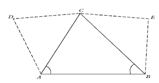
The position of another point C can be determined relative to the line AB by intersection (Figure below). The angles CAB and CBA are measured in the field, and the position of point C is obtained by plotting the two angles. Triangulation survey used for providing a large network of horizontal control points is based on the intersection by angles. The lengths of the sides AC and BC are calculated from the measured length AB and the angles, These calculated side lengths provide known distances for the adjoining triangles ACD and BCE. By solving these triangles, the lengths of all the sides are obtained. The calculated side lengths CD. DA, CE and EB become the known distances for additional triangles (not shown).
Intersection by distances
Alternatively, the position of point C relative to the line AB can be determined by measuring the horizontal distances AC and BC and not the angles. The process can be extended to adjacent triangles ACD and BCE by measuring the distances CD, DA, CE and EB. The chain survey is based on this method.
Modern trilateration survey in which EDM are used for measuring horizontal distances is also based on the method of intersection by distances.
Angle and Distance Method
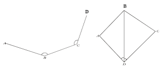
The position of point C with respect to the line AB can be determined by measuring .the horizontal distance BC mid the angle ABC (Below figure). This is the most direct way of determining the position of C. Traverse survey uses this method of fixing the position. After fixing the position of point C the position of the next point D is determined by measuring the horizontal distance CD and the angle BCD. The process is applied repetitively to succeeding points (not shown).
Resection
If the positions of three points A, B and C are known, the position of another point D can be determined by measuring angles ADB and BDC (Below figure). The position of D is determined graphically in plane table survey and by calculations in the theodolite survey. This method is known as resection.
Methods for Determining Heights
The position of a point in a vertical plane is determined by measuring its height with respect to some reference plane. The following three methods are used for determining the heights.
- Ordinary Spirit levelling
- Trigonometric levelling
- Barometric levelling
Ordinary Spirit Levelling
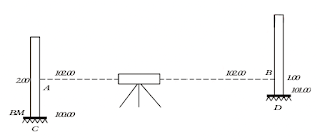
In this method, a spirit level is used to establish a horizontal line of sight. A levelling. instrument fitted with a telescope is used. In the below figure, the line AB is horizontal. The level of this line is determined by keeping a graduated rod, called staff, at the point of C known elevation, The level of the point D is determined by keeping the staff at D and taking the reading. In the figure, the height of the point D above C is 1.00 m.
Trigonometric Levelling
In trigonometric levelling, the difference of heights is determined using the principles of trigonometry. A horizontal line AB is first established with a theodolite. The height of the point C above this line is determined by measuring the horizontal distance D and the vertical angle θ
Barometric Levelling
The atmospheric pressure decreases as the elevation of a place increases. The difference of elevations of two points can be determined approximately by means of an accurate aneroid barometer, called altimeter, from the difference of atmospheric pressure at the two points. Generally, this method is used only in reconnaissance survey before starting the actual survey.


Post a Comment